ElectrifyingStacks on stacks on stacks. Caps on caps on caps. Also, no breadboards. As rules of thumbs, signal lines are physically separate from power lines, and twisted pairs are used when possible to reduce inductive noise. Power lines and signal lines are separated upstream to reduce conductive noise. Unnecessary lengths of wires are shortened to reduce stray capacitance. |

|
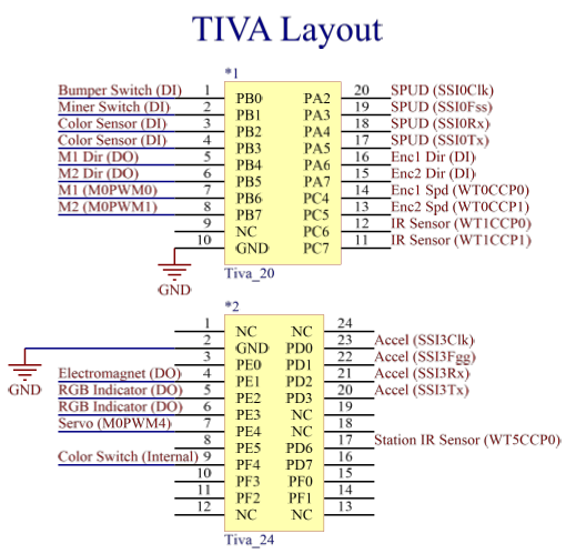
TIVA Pin-Out
|
All functionality is achieved using control from the TIVA microcontroller. Pins are allocated based on alternate function, which include:
|
Accelerometer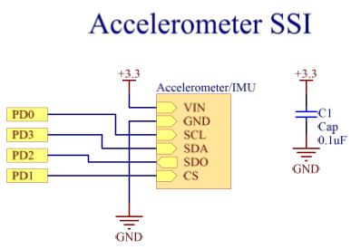
The accelerometer communicates to the TIVA via SSI on ports PD0, PD1, PD2, and PD3. 3.3V is supplied directly from the TIVA. A 0.1uF bypass capacitor acts to smooth the power line into the accelerometer. Electromagnet Gripper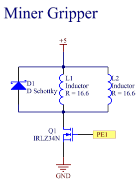
Two electromagnets used in parallel (and turned on via a low-side drive power MOSFET) allow us to grip the ferrous rim of the MINER beacon. A snubber diode is inserted in parallel to the magnets to limit voltage spikes after the magnets shut off. Contact Sensing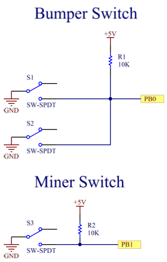
Simple switches act as contact-sensing for determining whether we had bumped into something or whether we had started to "grip" the MINER beacon. These switches are connected to input pins on the TIVA. Motor Encoders
Motor encoders used per specifications from manufacturer: https://www.pololu.com/product/4761 Encoder ticks from OUTA are connected to input capture pins on the TIVA for both the left and the right motor. The OUTB ticks are used to determine motor direction via quadrature. Red-Blue LED Indicator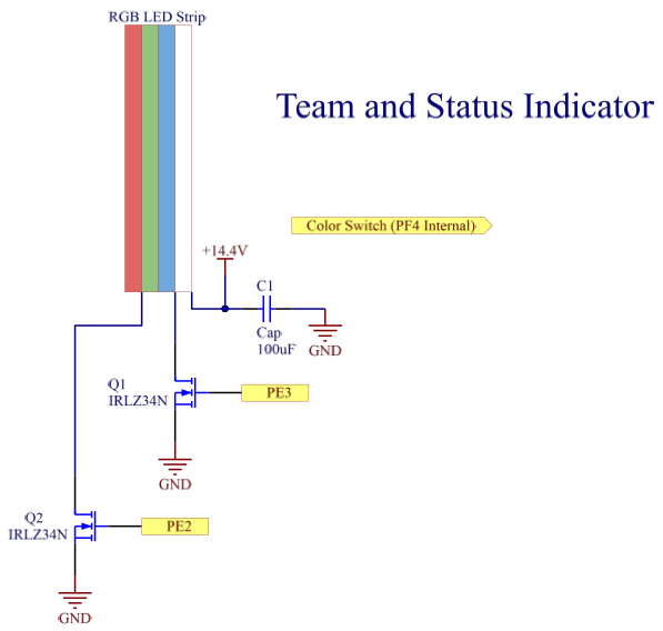
The RGB LED strip runs on 14.4V in low-side drive configuration. Power MOSFETS are used to account for the higher amounts of current when running the LEDs. MOSFETs are controlled via output pins on the TIVA. |
Beacon ServoThe servo is driven by PWM-enabled port PE4 of the TIVA. Position control is achieved by sending corresponding-width pulses to the servo. Infrared Detection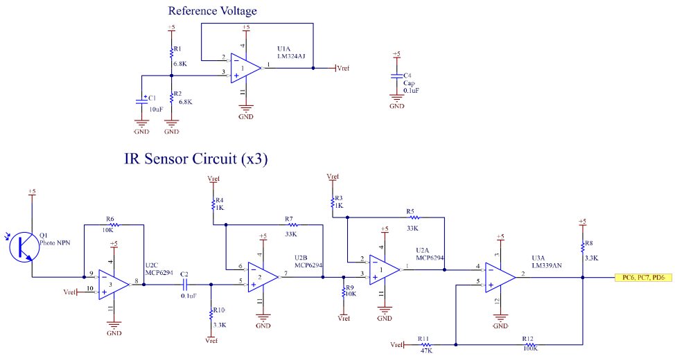
Infrared light enters an NPN phototransistor, which is tied to 5V, to generate a current. An MCP6294 op-amp in a trans-resistive configuration converts the current into a voltage. The signal passes a high-pass filter to attenuate DC signals. The signal then enters a pair of gain stages, which when combined, offer a total gain of ~1000. Finally, the signal enters a comparator (LM339) with hysteresis to convert the signal into a digital high or low for microcontroller input. The input of each amplification is pulled to ground to stabilize the signal from external noise sources. Motor Driver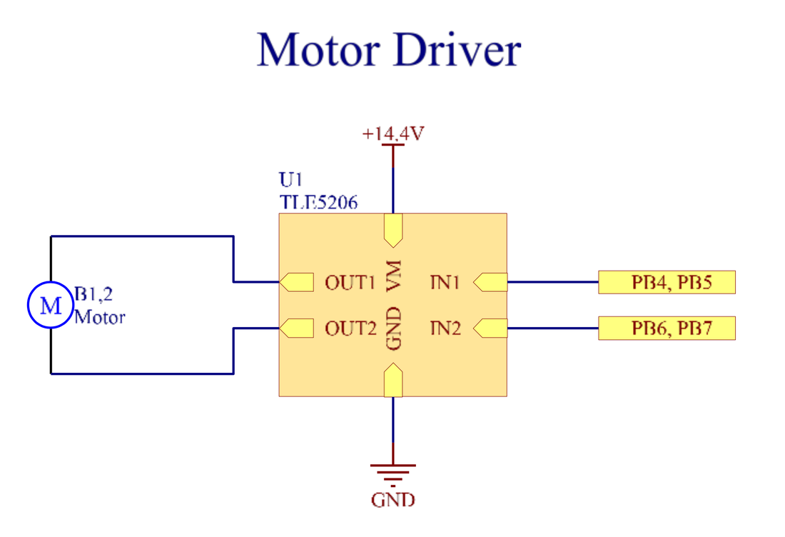
TLE-5206-2 drivers are used to drive the motors for several reasons: 1. TLE5206-2 is a MOSFET-based driver. Compared to BJT-based drivers that have 1.2V emitter-collector drops, the voltage drop for TLE5206-2 with ~60 ohm motors and 500mH Rds(on) is ~0.12V. 2. At 14.4 V nominal voltage, the motors at peak operation can draw 240mA each, which is well below the 5A continuous current limit of the TL5206-2. Power Distribution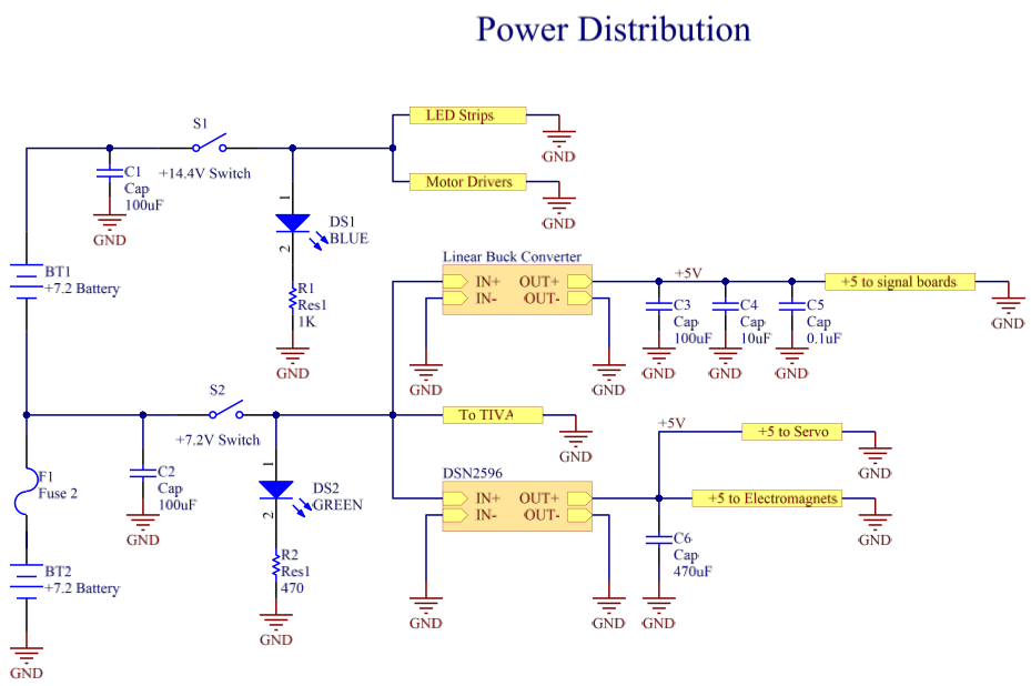
Two 7.2V NiMH batteries deliver a 7.2V and a 14.4V line to Business Bot. Each line can be toggled on/off through separate switches and monitored through LEDs. A 5A fuse prevents current overloads from breaking downstream circuits and components. The 7.2V terminal powers the TIVA directly, as well as linear and switching converters. The more stable 5V output of the linear converter drives the signal boards, while the less stable switching converter delivers 5V to the servo and electromagnets. The 14.4V terminal delivers power to the LED strips and motor drivers. "SPUD" SPI Communication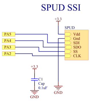
SPUD communicates to the TIVA via SSI on ports PA2, PA3, PA4, and PA5. 3.3V is supplied directly from the TIVA. A 0.1uF bypass capacitor acts to smooth the power supply into the accelerometer. |
